other posts
-
Mar 19, 2018
Nod-o-Meter
-
Jan 23, 2018
variational autoencoder interactive demos with deeplearn.js
-
Sep 15, 2017
backpropagation using random feedback weights
-
Jun 16, 2017
quora question pairs
Intro
In a previous life, I was the founder of Serene Audio. Where we made the best compact desktop speakers. Part of what made the speakers so great was their built-in amplifier that I designed. It had a DSP chip which allowed me to tune the amplifier to the specific properties of the transducers and their enclosure. We decided to shut Serene Audio down last year. It was a difficult decision, but that's another story.
I decided to open the design of the amplifier for the benefit of the DIY audio community. I have attached all the gerber files, but also the DipTrace schematics, layout, and BOM files. DipTrace is the software that I used, and I highly recommend it. It is very user-friendly, but also affordable. You can use it to a modify and adapt the design for your own needs.
Note on emi
We have been through 4 iterations of this design. So most of the kinks are ironed out, but there are some things to consider. First, this uses a digital amplifier chip (TAS5708), and EMI is a concern with D class amps. I have not done any EMI testing, however I have paid close attention to controlling EMI in circuit and layout design.
Hardware
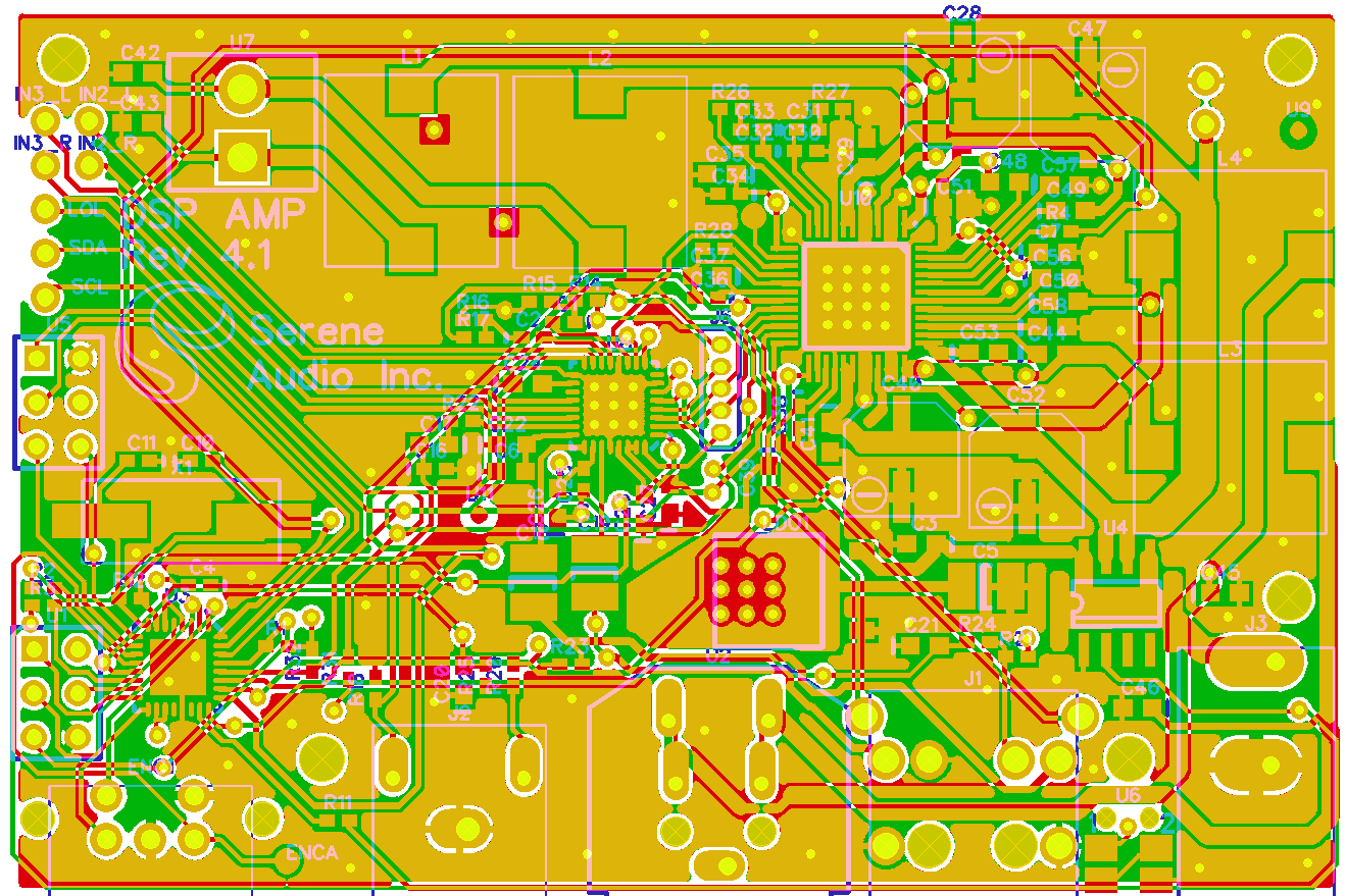
The layout is a 4 layer board. Where 2 middle layers are ground & 3.3V, and the top & bottom layers are signal layers. I have paid close attention to the return paths of currents to avoid EMI, but I've also tried to isolate the analog and digital return paths to improve SNR. Some of the features are:
Header for easy programming of the MCU with Atmel AVR ISP mk2
I2C header for possibly communicating with external devices
I2S header for by passing PCM3070 internal ADC. (e.g. If you use your computer as a source, you can add a USB to I2S chip to eliminate the ADC and improve SNR)
Analog audio input headers. PCM3070 has 3 stereo inputs. One is routed to the 3.5mm jack. The other two are available in the headers, and they can be combined to form a balanced input.
The amp can deliver 20W/channel to 8Ohm loads.
It can also work with a voltage range of 12V to 24V.
Compact design; the PCB is about 3x2 inches.
PIO header
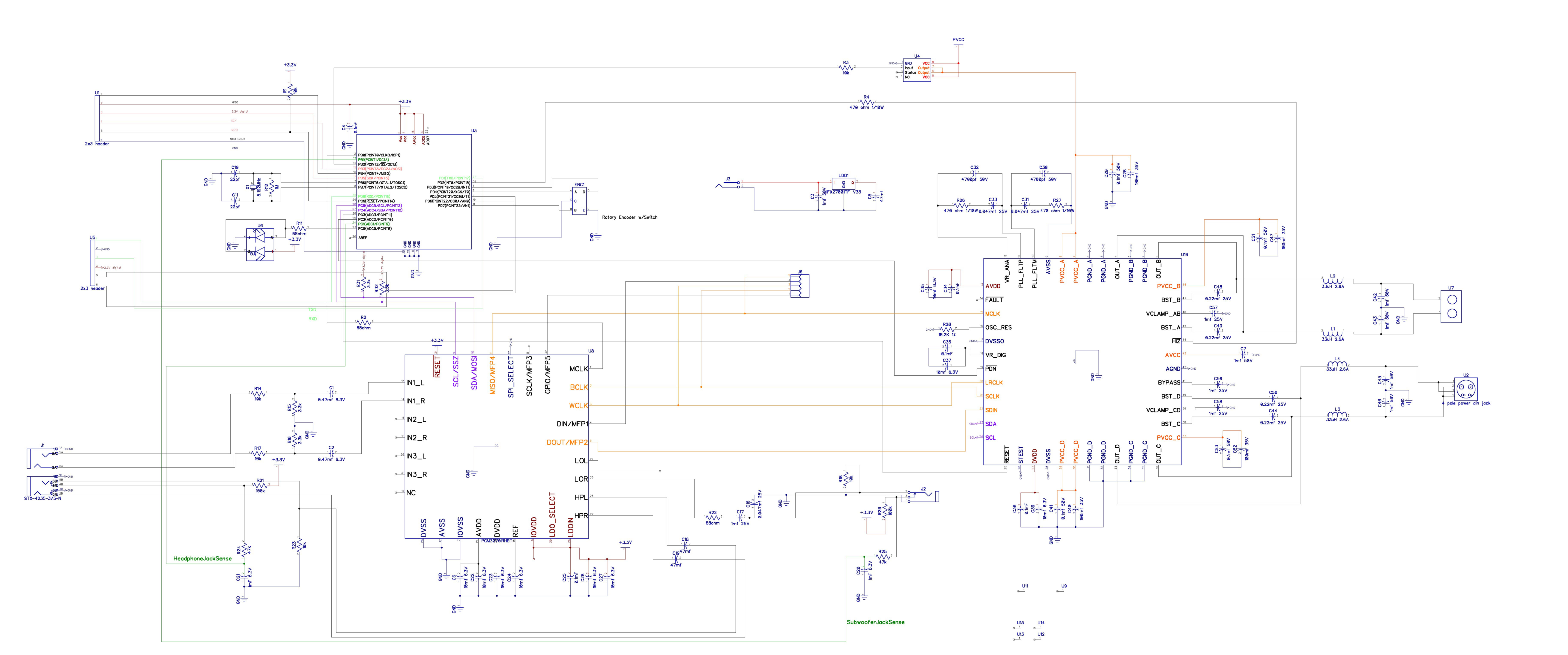
The main components of the circuit are:
An Atmel atmega328p MCU which is the brain of the system.
Texas Instrument's PCM3070 which I use for ADC, DAC, headphone out, and DSP
Texas Instrument's TAS5708 which is a closed-loop 2 channel D-class amp with I2S interface.
The MCU holds the configuration for both PCM3070 and TAS5708. It communicates with these chips through I2C interface. It also interfaces with the digital encoder and switch that acts as volume knob and power button. The subwoofer output also has a built-in switch, using which, the MCU detects when a subwoofer cable is plugged in and then activates a high-pass filter in PCM3070.
Firmware
What makes the amp really useful is its programmability. All the DSP coefficients and configurations are stored on the MCU itself. The MCU can be programmed using an Atmel AVR ISP mk2 through the header right behind the encoder. I used the Arduino platform for developing the firmware. Here is a link the Github repo of the firmware. The firmware consists of for files:
MCU_code.ino which is the main file that has all the logic for handling interrupts and configuring PCM3070 and TAS5708.
REG_Section_Program.h which has all the configurations of PCM3070 (Things like clock configurations, signal routing, gains, etc.)
TAS5708.h which has all the configurations and DSP coefficients of the TAS5708 chip. (TAS5708 has a simple DSP buit-in, but I'm not using it.)
main_Rate48_pps_driver.h This file contains the DSP coefficients for the two miniDSP cores inside PCM3070.
Customizing the DSP
Texas instruments offers a drag and drop graphical UI that makes programming PCM3070 significantly easier.
It is called PurePath Studio. You can download it for free from their website.
You can use this software to configure the DSP to your heart's content to make your speakers really shine.
The contents of main_Rate48_pps_driver.h are directly copied over from a file generated by PurePath Studio by the same name.
Note: When copying over the data, make sure you add the PROGMEM modifier. It directs the compiler to store the values in flash memory instead of SRAM.
Final notes
I have some PCBs left over from our last batch. I can mail you one for free, just shoot me an email if you want one. To make your own, you'll have to order your own components and solder paste stensil. Then manually place the components after applying the paste, and bake. It is a very delicate process, but I had success on my first try.
Let me know in the comments if you have any questions or if there is anything I missed.